
Access to source
( translation in progress ! This page uses the "greek.ttf" font )Home Companime/ Immersion homepage/ comPanrama Console/ Software detail of the calculation
Access to source
|
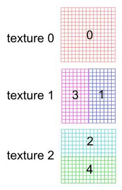
Obtaining of 5 images in classic perspective and keeping these images in memory, without showing them. In the agreement OpenGL, by default the camera is originally centred and looks toward negative Z. The camera remains centred originally, but is successively steered towards: - Image 0: Z negative -> texture 0 - image 1: X negative, (rotY 90 °) -> texture 1 ( straight(right) part(party)) - image 2: Y negative, (rotX 90 °) -> texture 2 (bottom) - image 3: X positive, (rotY 90 °) -> texture 1 ( straight(right) part(party)) - image 4: Y positive. (RotX 90 °) -> texture 2 (top)This is my agreement. Apparently each makes as one pleases in this domain. The camera has an opening of 90 ° horizontally and vertically. Only the face 0 is whole. The sides are only half-faces. We use the glFrustum function which allows to film a half-face. The extension FBO (Frame Buffer Object) allows to register the images as texture without showing them (without sending them to the Frame buffer). [ See in source the module PanCamera.cpp and the function CPanCamera::shot ()] | 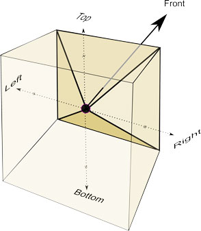 |
 |
 |
 |
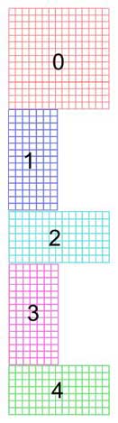
The "opened" camera-cube |
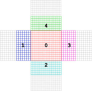
Original linear mesh |
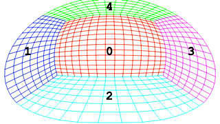
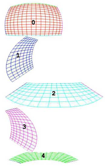
Destination mirror mesh |
 |
 |
 | |
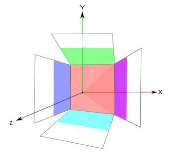
Configuration of textures |
Mesh " linear " |
Mirror-Mesh |
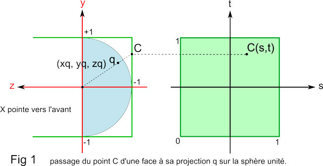
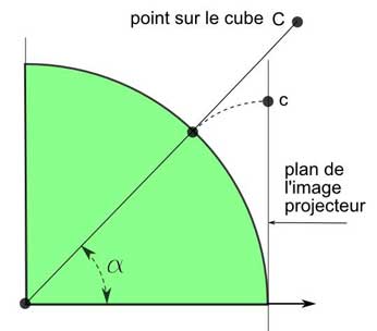
| A point C of a face of the cube is represented by its texture coordinates (s, t), s and t varying from 0 to 1 (imposed by OpenGL). |
But the point C also has spatial coordinates x, and z such as, for every face:
 Face 0 x = 2s-1 = 2t-1 z = 1 front
 face 1 x =    1 = 2t-1 z = 1-2s left
 face 2 x = 2s-1 = 1    z = 1-2t bottom
 face 3 x =    1 = 2t-1 z = 2s-1 right
 face 4 x = 2s-1 =    1 z = 2t-1 top
The point C has for image the point q situated on the sphere unity framed in the cube: If L is the distance from the centre of the sphere unity to the point C situated on the face, we have: L = Square root (x2 + y2 + Z2) Xq = x/L yq = y/L zq = z/L [ See in the class CMesh the functions build_fisheye() and build_miror()] |
 |
System with fisheye
Calculation of the inverse way: function CMesh::xyz_fisheye_uv )
|
If the system is centred (the optics and the dome have the same axis) the calculation is simple. ( Otherwise (that I did not study), we are close to a system with mirror). ( X, z are the coordinates of a point C situated on the cube camera) ( U, v are the coordinates of the point c corresponding in the image projector) Three stages: - Calculation of the angle Q between the horizontal plan (ox, oz) and the plan passing by C and oz. - Calculation of the angle a between oz and oC. - Module of the point c. In fact we "unwind" the half-sphere on the tangent plan. [ To know more about it, see Mesh.cpp et Mesh.h source] |
 |
|
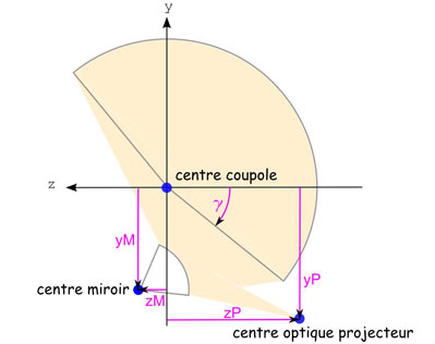
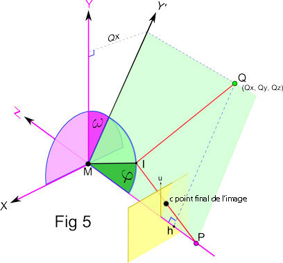
We need two reference systems: 1) The first one zy (small letters) serves for defining the physical configuration of the console. It is used to communicate this configuration with the comPanConfig software. Three elements compose the console: dome, mirror, projector, The dome, because of its size, is the most stable Adjustments are made by moving the mirror or the projector). We thus take as origin the centre of the dome. The axis y is vertical, The axis z is directed in the direction "projector --> mirror". ( This is coherent with OpenGL). The coordinates of the mirror are thus zM and yM (yM is negative on the figure) Those of the projector zP and yP (both negative on the figure) The dome is tilted by an angle (gamma) (approximately 45 ° on the figure) |
 |
|
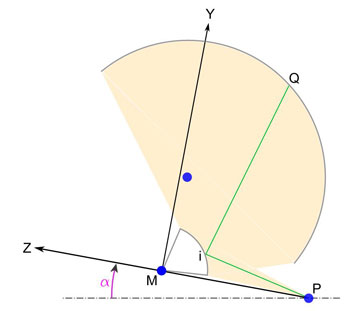
2) The second ZY (capital letters) is thr internal system of reference for calculation. We need to know it only to understand source of the software. The origin is taken in the center of the mirror Mr. The axis Z passes by the projector. It is still steered in the direction projector > mirror. The axis X is horizontal, steered towards us. This referential is tilted by an angle (alpha) with regard to the precedent. ( Approximately 20 ° on the figure) We apply a factor of scale which returns the radius of the mirror equal to 1. The scale has, in fact, no importance because the resultant mesh will be at first normalized there (O, 1), then fitted to the definition of the image (on 1280 in my case). |
 |
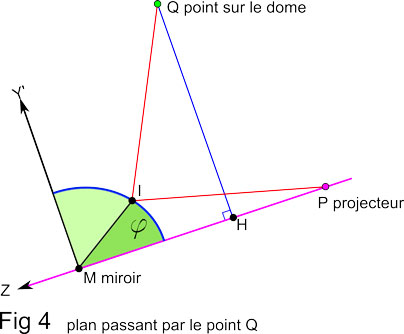 |
Let us consider the plan ZY' which contains points M, P, Q and I (it makes an angle w with the vertical plan ZY): In this plan the coordinates of Q are (MH=Qz,HQ) Coordinates of P are Pz (Py == 0) The segment IQ has for constituents Qz - cos (f) and Qy - sin (f) |
The difficulty of the calculation comes down to determine f so that the expression:
 be minimal.
|
We do not know how to calculate directly such an expression. It is necessary to appeal to a technique of successive estimates. ( Fortunately there is always some Internet user of willingness who gives his work and made win a lot of time). This calculation is relatively slow. But we calculate the meshes only once. In summary, the point Q, situated on the dome, |
 |